Other Kits for DIY audio projects
Low Voltage Power Supplies
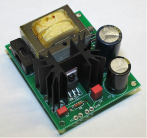
After cobbling together untold numbers of small power supplies for “auxiliary” functions in tube preamps and power amps, I decided to design something with a regulator that is better than the ubiquitous 7800 series three terminal regulator and try it in places where it powers something more than relay coils. In locations like low voltage negative supplies and as power for a USB to SPDIF digital audio converter I found this supply sonically superior to my previous slapdash efforts. These power supplies use either the LT3080 or its big brother the LT3083 regulator, which are adjustable by changing one resistor for output voltages between 1 and 24 volts DC for the LT3080 and 18 volts DC for the LT3083 in this implementation. A charging slope lowering resistor and Schottky rectifier diodes are provided to be kind to the power transformer and reduce both supply noise and radiated magnetic field noise. Along with plenty of output bypass capacitance, this compact package does a thorough job of supplying up to 4 watts of power or 12 watts of power at low voltages. Resistors are provided for 5, 6.3, and 12VDC. You can obtain other 0.25w resistors for other voltages. The supply can accommodate both 115V and 230V mains voltage and has an on-board fuse holder for safety.
With the standard supplied 8+8 volt secondary power transformer, the maximum possible DC current draws are listed below. If you are using one of these supplies for tube filaments, you will get the greatest output current with a 6.3+6.3 volt secondary power transformer, so request that you receive this power transformer for filament supplies.
4 watt Version
- 5VDC 870mA
- 6.3VDC 700mA
- 12VDC 470mA
The PC board is 2.75″ (7cm) x 3.3″ (8.4cm) and the height is 1.6″ (4cm).
Low Voltage 4 watt Power Supply Kit: $38
12 watt Version
- 5VDC 2A
- 6.3VDC 2A
- 12VDC 1.2A
The PC board is 3.2″ (8cm) x 4.2″ (10.7cm) and the height is 2.1″ (5.3cm).
Low Voltage 12 watt Power Supply Kit: $52
Low voltage power supply (4 watt)
Two Terminal Constant Current Source
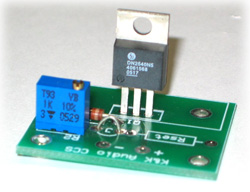
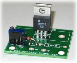
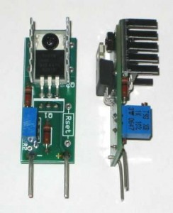
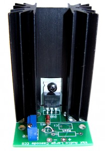
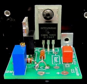
These products are based on the sonically transparent IXYS IXTP08N100D2 depletion mode MOSFETs to enable constant current operation of tube circuits without having to worry about a source of bias. They are very simple and easy to integrate into existing designs. Use current sources to provide excellent balance in “long-tail” pair differential circuits or to obtain highly linear constant current triode operation as a plate load. Add a heat sink kit for operation at higher levels of power dissipation. Several versions are offered: an economical basic current source with very good performance, a cascode current source for improved measured performance and a slight sonic improvement, a large cascode current source that accommodates an even larger heat sink, a cascode current source that is configured so the MOSFET can be attached to the chassis or a very large heat sink for high current/voltage operation, and a compact cascode current source that is small enough to be used to replace resistors for easy upgrading to constant current operation. These kits feature current adjustability over a wide range (some start as low as 2.5mA and others start at 10mA; the maximum is 100mA) and space for a fixed resistor to replace the variable resistor once the “correct” current has been determined. The minimum operating voltage is 10VDC + 1/2 peak-to-peak AC signal amplitude for the Basic Kit and 20VDC + 1/2 peak-to-peak AC signal amplitude for the cascode kits while the voltage rating maximum is 1000VDC for all of the kits.
PC board sizes:
- Basic CCS – 1.55″ (4cm) x 1.2″ (3.1cm)
- Cascode CCS – 1.55″ (4cm) x 1.3″ (3.3cm)
- Large Cascode CCS – 1.75″ (4.5cm) x 1.7″ (4.3cm)
- Attachable Cascode CCS – 1.3 (3.3cm)” x 1.2″ (3.1cm)
- Compact Cascode CCS – 1.7″ (4.3cm) x 0.7″ (1.8cm)
| Basic Current Source Kit (up to 1 watt without a heat sink) | $10 |
| Cascode Current Source Kit (up to 1 watt without a heat sink) | $14 |
| Small Heat Sink Kit (up to 3 watts) | $3 |
| Large Heat Sink Kit (up to 5 watts) | $3.50 |
| Cascode Current Source Kit attachable to an external heat sink (up to 20 watts with adequate heat sink) | $15 |
| Compact Current Source Kit (up to 2 watts w/included heat sink) | $16 |
| Large Cascode Current Source Kit (up to 7 watts w/included heat sink) | $20 |
Two Terminal Cathode Current Sink
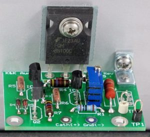
This current sink was developed specifically for the purpose of acting as a cathode CCS in medium to high current applications. I have used the simpler basic and cascode current sources described above for cathode current sinks and they have two limitations. For higher current applications, such as tube power amp output stage cathode current sinks, under some circumstances they oscillate, rendering them useless. The other disadvantage is that the temperature coefficient of the basic and cascode current sources is rather high. In contrast, the Two Terminal Cathode Current Sink has proved to be oscillation free in extensive beta testing in both SE and PP designs over a wide range of currents. The Current Sink is also designed to have a very low temperature coefficient, so the stage using the Current Sink will sink the same current in the first minute of operation as it will an hour later after the amplifier has warmed to operating temperature. I (and others) have tested it in amplifiers over the range of 100mA to 400mA, but don’t take these as application limits, as it’s certainly usable at lower currents and at higher currents, subject to the use of an appropriate heat sink. It is set up so that it’s a two terminal CCS, but has a 400VDC limitation between the + and – terminals. For best performance at cathode voltages less than 40VDC provision is made to supply the reference current separately from a higher voltage point in the amplifier circuit (up to 400VDC). The current is adjustable by means of a 2w resistor in parallel with a 50R trim pot. The 2w resistor choice defines a relatively narrow range within which the trim pot is used to “fine tune” the current. There are also test points at both ends of a 1ohm resistor to allow for indirect current measurement.
The PC board is 1.8″ (4.6cm) x 1.3″ (3.3cm).
Two Terminal Cathode Current Source Kit: $28
Cathode Current Sink
(shown attached to a heat sink)
High Voltage Shunt Regulator Kits
This combined current source / shunt regulator kit has been designed to provide a high quality, simple-to-implement regulator to isolate amplifier input stages from the output stage and raw power supply or to provide high quality power supply isolation for line stages or phono stages.
The current source part of the circuit is identical to that used in the Cascode Current Source Kit. The shunt regulator circuit is similar to that originally developed by Salas (http://www.diyaudio.com/forums/power-supplies/134801-simplistic-mosfet-hv-shunt-regs.html). It’s a simple circuit that performs very well, like the cascode CCS, and is stable under a variety of operating conditions. The shunt regulated voltage is set by a simple JFET current source, which controls the shunt transistor by means of a driver transistor. An RC network across the output manages the transient response to provide quick recovery from transient demands without significant overshoot. The regulated voltage is adjusted using a trimpot that sets the current through the reference current source.
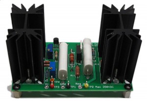
The combination of the current source and the shunt regulator provides all that’s necessary for a simple first-class high voltage regulator. There are two versions of this circuit with different voltage ranges. The 100V-350V version uses board mounted heat sinks and is applicable to many phono stage, line stage and amplifier input stage applications. The 300V-600V version is similar in size and appearance to the lower voltage version, but is optimized for a higher voltage range.
To determine if either kit meets the needs of your circuit and to properly specify the heat sink size, you should read the instructions (High voltage regulator manual and Low voltage regulator manual ) and do the simple calculations necessary to determine how tall the board-mounted heat sinks need to be.
The PC board dimensions are:
- 100V-350V version: 3.9″ (9.9cm) x 2.3″ (5.9cm)
- 300V-600V version: 4.6″ (11.6cm) x 2.3″ (5.9cm)
Both kits have the potential to add from 1″ (2.5cm) to 2.5″ (6.4cm) tall heat sinks. If not specified otherwise, 2.5″ (6.4cm) heat sinks will be supplied.
Shunt Regulator Kit, 100V-350VDC $52
Shunt Regulator Kit, 300V-600VDC $60
Time Delay and Soft Start Kits
It is often very useful to delay the application of the high voltage in a tube circuit until the tube filaments have had several seconds to warm up. This prevents the phenomenon known as “cathode stripping,” where the presence of full voltage to the tube’s electrodes before the cathode is at emitting temperature prematurely depletes the coating on the cathode that is responsible for the electron emission which, in turn, makes the tube work. In a choke loaded power supply design, delaying the application of high voltage until filament warm-up has been achieved also prevents the large over-voltage event that accompanies a sub-critical load for the choke.
In addition, if you find the use of a tube rectifier not to be to your sonic taste, but still desire the “soft start” action implicit in the rectifier filament warm-up, this action can be imitated using a low impedance solid state circuit that is virtually out of the circuit once the voltage has risen to its maximum.
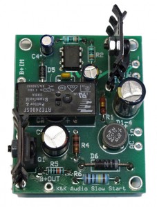
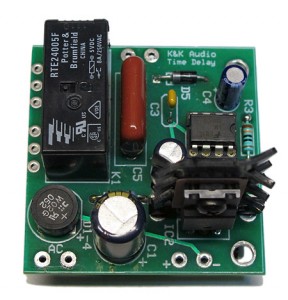
There two kits that address these needs. After a fixed time delay the Time Delay Kit circuit closes a relay that can control the B+ voltage or even the B+ transformer mains voltage, in the case of a separate B+ supply. The time delay is set for 30 seconds by a supplied resistor, but can be changed over a wide range by changing the value of that resistor. The Soft Start Kits incorporate the same time delay circuit to switch the B+ voltage followed by a MOSFET circuit that ramps that voltage up over about 30 seconds, so full B+ is achieved after about a minute. The Soft Start Kit supports loads up to 200mA and the High Current Soft Start Kit supports loads up to 500mA.
The Time Delay Kit PC board also accepts a small relay that can be used to add a time delayed mute function to any preamp, so that at power up and for 30 seconds afterward the outputs are shorted by the relay contacts. Once the 30 seconds (or whatever time you want to use) has passed, the relay contacts open and the audio signal is unimpeded. Many tube preamps pass an “ugly noise” onto the amplifier during initial warm-up that this action prevents.
The same PC mount power relay is used in both circuits and is rated for a hefty 8 amps. These relays have been used for years in products switching B+ voltages as high as 550V with no problems. Either circuit can be powered by 6-12VAC or 7-25VDC and draws less than 200mA with the relay actuated.
PC board sizes:
- Time Delay Kit – 1.9″ (4.8cm) x 1.9″ (4.8cm)
- Soft Start Kit – 2.4″ (6.1cm) x 1.9″ (4.8cm)
- High Current Soft Start Kit – 3.4″ (8.6cm) x 2,5″ (6.1cm)
Time Delay Kit $28
Soft Start Kit $38
High Current Soft Start Kit $52
Inspirations: Music for Solo Flute 
Catherine LeGrand, Flutist
Classical Flute Music composed by C.P.E Bach, Hildegard von Bingen, Astor Piazzolla, Claude Debussy and others
This CD was recorded by Kevin Carter using an all-tube analog signal chain direct to a hard drive at 20 bit 88.2kHz resolution. Cad VX-2 vacuum tube microphones were placed in a Blumlein figure 8 crossed pair and amplified by a custom K&K Audio designed and built Lundahl transformer-coupled (using LL1550 and LL1660/PP transformers) microphone preamplifier.
To purchase this CD go to www.in1breath.com

