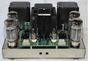
Single-Ended Amplifier Input Stages
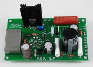
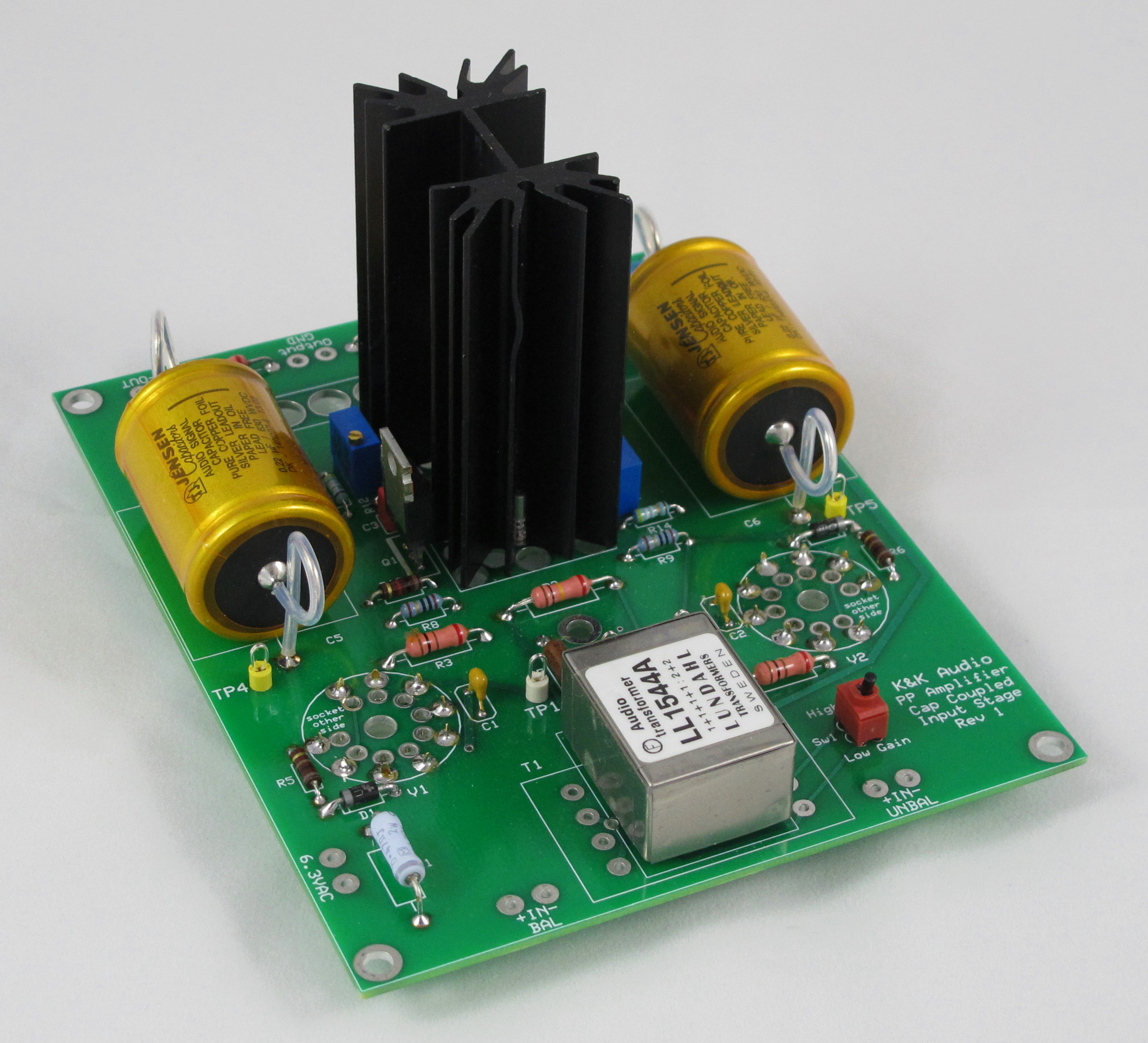
Single-Ended Amplifier Input Stage Kit (shown configured for capacitor coupling with input grid choke)
Single-Ended Amplifier Input Stage Kit (shown configured for capacitor coupling with input grid choke)
We have developed a single-ended (SE) input stage with relatively high gain, making it possible to build a two stage amplifier with adequate input sensitivity to work in a wide range of audio systems, not just systems that use high sensitivity speakers. There are two coupling options built into this kit. One uses a Lundahl interstage transformer while the other uses the more common capacitor coupling method. It’s possible to outfit the kit with a grid choke on the input tube, as an option, as well.
The tube type used in this input stage is a class of high transconductance pentodes that are connected for operation as Class A triodes. These tubes have the advantage of very high gain (>50) and moderately low plate resistance, making them really useful for this type of input stage. The Russian 6J49P is supplied with the kit, but other tubes in this “family” can be used, as well, with only minor modifications required, if any.
The kit’s circuitry includes RC power supply filtration for the input stage as well as a capacitor stage for the output tube. This added stage of filtration was originally designed into the SE input board to complement the Lower Voltage Amplifier Power Supply Kit for use in a SE 6C33C amplifier, but can be used for any output tube that will operate off of voltages less than 400VDC. For higher voltage output stages, a higher voltage capacitor can be located off-board and wired into the capacitor pads. Either the interstage transformer (LL1692A/14mA) or the cascode current source plate load is fed from the on-board RC filter. The input stage tube coupling method is chosen by means of a jumper on the PC board and pads on the edge of the PC board. The grid leak resistor for the output tube is also on the PC board, with a pad to connect it through an off-board gate stopper to the grid connection at the socket. The cathode bypass capacitor for the output tube is likewise provided for on the PC board, with pads for external cathode bias resistor(s) or current source, if used. By this means there are relatively few parts in the amplifier that don’t have a home on a PC board (Input Stage or Power Supply) that provides a consistent, tested layout, minimizing the chance for circuit oscillation and the attendant bad sound.
The SE Input Stage Kit is available with and without a Lundahl LL1670 grid choke at the input. Grid chokes provide a relatively high impedance load for the incoming audio signal, but are at the same time a low resistance path to ground for grid bias current. This tends to stabilize the input tube and make the combination of a high transconductance input tube and long interconnect runs more compatible without resorting to sound-softening values of grid stopper resistors, etc.
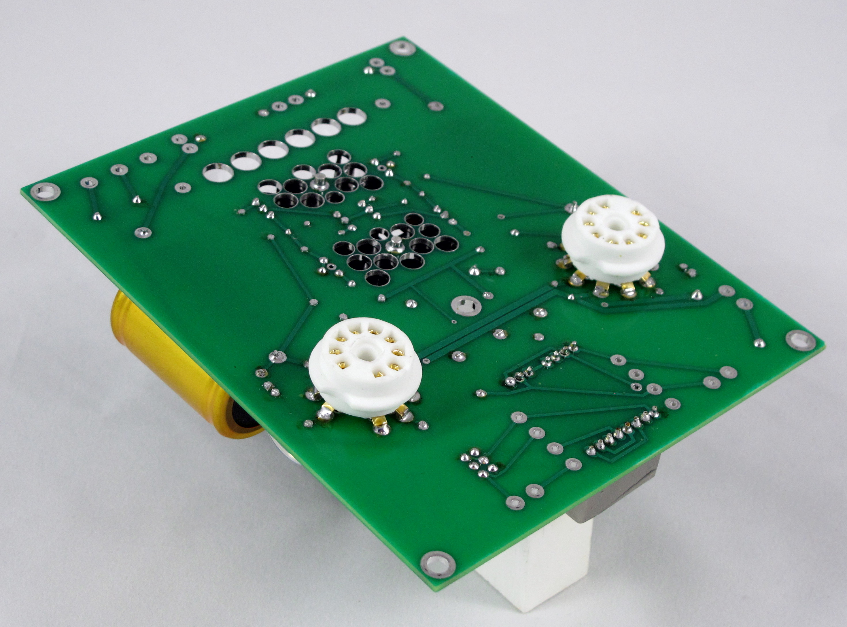
The input stage kit provides a complete input stage to drive the output tubes of your choice. You will need to supply the high voltage power supply (see our kits for this) and the AC filament supplies, as well as the output tubes and sockets, grid stopper resistors, the output transformer (there are many Lundahl transformers to choose from here) and the components necessary for the type of output stage biasing you have chosen. The input stage PC board is designed so the tube socket solders on the opposite side of the board from the rest of the components. This allows you to mount the boards under the chassis top leaving only the input tube showing.
Capacitor Coupled SE Input Stage Kit
- Gain: 34dB@1KHz
- Maximum Output Level: 110VRMS (310VP-P) @ 3%THD+N
- Frequency Response: -0.2dB @ 20Hz and -1.0dB @ 100KHz (reference 1KHz)
- (All measurements are made with optional grid choke installed and equipped with Russian 6J49P tubes)
- PC board with grid choke is 3.4” (8.6cm) x 5.8” (14.7cm). PC board without grid choke is 3.4” (8.6cm) x 4.9” (12.5cm). The assembled input stage requires about 3” (7.6cm) clearance under the top plate for mounting.
$109 per channel with Jantzen Audio Z-Cap Superior capacitor without grid choke
$179 per channel with Jantzen Audio Z-Cap Superior capacitor and grid choke
Interstage Transformer Coupled SE Input Stage Kit
- Gain: 33dB @1KHz
- Maximum Output Level: 100VRMS (280VP-P) @ 3%THD+N
- Frequency Response: -0.9dB @ 20Hz and -6dB @ 66KHz (reference 1KHz)
- (All measurements are made with optional grid choke installed and equipped with Russian 6J49P tubes)
- PC board with grid choke is 3.4” (8.6cm) x 5.8” (14.7cm). PC board without grid choke is 3.4” (8.6cm) x 4.9” (12.5). The assembled input stage requires about 3” (7.6cm) clearance under the top plate for mounting.
$89 per channel without either the grid choke or the interstage transformer (call to discuss IT requirements)
$150 per channel with the grid choke, but without the interstage transformer (call to discuss IT requirements)
$199 per channel with the LL1692A/14mA and PC board for wiring it, without the grid choke
$269 per channel with the LL1692A/14mA and PC board for wiring it, including the grid choke
Teflon tube sockets with collet style contacts are available as an option for either type of kit (replacing the standard gold plated contact ceramic sockets) for $17.50 per channel.
Push-Pull Amplifier Input Stages
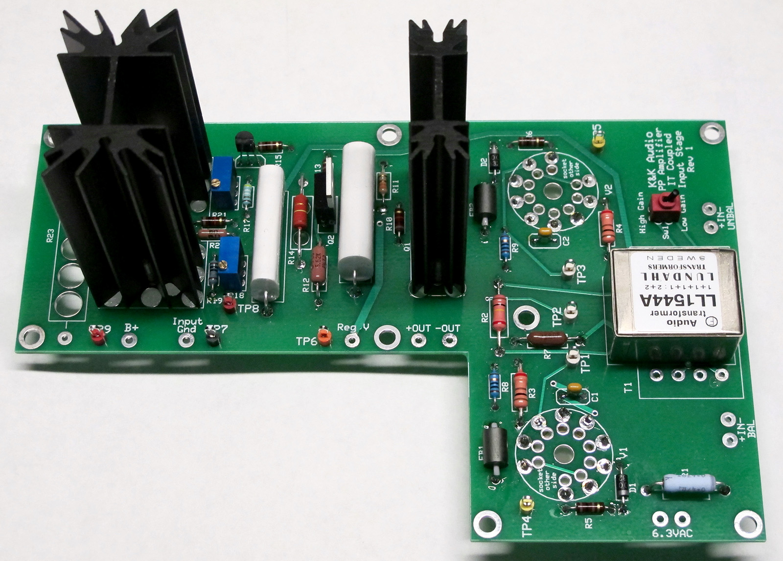
We have developed a pair of push-pull input stages with relatively high gain, making it possible to build a two stage amplifier with adequate input sensitivity to work in a wide range of audio systems. The two input stage kits differ in the method used to couple the input stage to the output stage. One uses a Lundahl interstage transformer while the other uses the more common capacitor coupling method.
These push-pull amplifier input stages are quite different from most of the others that have been and are available, in that the signal phase splitting is accomplished with an input transformer rather than by using a tube stage. While much has been made of the band limiting and distortion characteristics of transformers in the audio press over the last 50 years, it is my experience that the sound quality that results from phase splitting in an input or interstage transformer easily exceeds that achieved by even the highest tech tube phase splitting circuit. The performance of the transformer within its bandwidth is very consistent, rendering very accurate phase splitting from well below 20Hz to well above 20KHz.
In addition, the input transformer provides galvanic isolation between the source and the amplifier, removing the possibility of ground loop hum involving the power amplifier, a common problem in audio systems. In these input stages the input transformer is followed by a relatively high gain triode-connected pentode differential stage that drives the output tubes through either coupling capacitors or an interstage transformer. This stage, often referred to as a “short-tailed pair driver,” provides gain and symmetrical drive to the output stage at a moderately low impedance. The tubes used in these input stages are high transconductance pentodes that are connected for operation as Class A triodes. These tubes have the advantage of very high gain (>50) and moderately low plate resistance, making them really useful for this type of input stage. Matched pairs of the Russian 6J49P are supplied with the kits, but other tubes in this “family” can be used, as well.
The interstage transformer coupled input stage is fed at the primary center tap of the interstage transformer from an on-board shunt regulator (see the Shunt Regulator kits for details of that circuit) that removes the vast majority of power supply artifacts, providing greater detail and soundstage information retrieval. The capacitor coupled input stage uses current source plate loading for the pentode-connected triodes to provide good power supply noise rejection and the best load characteristics. Space is provided on either PC board for a 10 watt voltage dropping resistor for use when higher (>400VDC) main B+ voltages are needed for higher voltage output tubes. A specific resistor value is not provided as it will vary with the B+ used in your design. The instructions provide the information necessary to calculate the value needed.
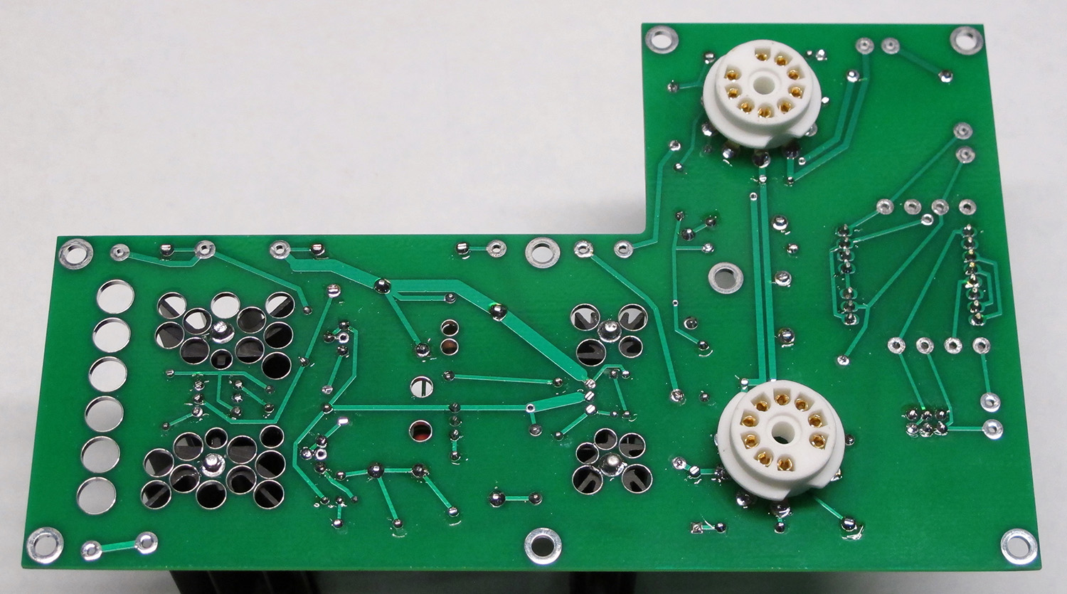
Either input stage kit provides a complete input stage to drive a pair (or more) of the output tubes of your choice. You will need to supply the high voltage power supply (see our kits for this) and the AC filament supplies, as well as the output tubes and sockets, grid stopper resistors, the output transformer (there are many Lundahl transformers to choose from here) and the components necessary for the type of output stage biasing you have chosen. The input stage PC boards are designed so the tube socket solders on the opposite side of the board from the rest of the components. This allows you to mount the boards under the chassis top leaving only the input tubes showing.
Capacitor Coupled Push-Pull Input Stage
- Gain: 39.9dB @1KHz
- Maximum Output Level: 225VRMS (630VP-P) @ 3%THD+N
- Frequency Response: -0.9dB @ 20Hz and -1.7dB @ 100KHz (reference 1KHz)
- (All measurements are with input transformer gain set to “High” measured from +OUT to –OUT equipped with Russian 6J49P tubes)
- PC board is 4.3” (10.9cm) x 5.3” (13.5cm). The assembled input stage requires about 3” (7.6cm) clearance under the top plate for mounting.
$225 per channel with Jensen Capacitor copper foil in oil capacitors
$199 per channel with Jantzen Audio Z-Cap Superior capacitors
Interstage Transformer Coupled Push-Pull Input Stage
- Gain: 38.4dB @1KHz
- Maximum Output Level: 187VRMS (525VP-P) @ 3%THD+N
- Frequency Response: -0.9dB @ 20Hz and -6dB @ 58KHz (reference 1KHz)
- (All measurements are with input transformer gain set to “High” measured from +Grid to –Grid equipped with Russian 6J49P tubes)
- PC board is irregular in shape, accommodating the IT, for a combined dimension of about 5.6” (14.2cm) x 6.8” (17.3cm). The assembled input stage requires about 3” (7.6cm) clearance under the top plate for mounting.
$199 per channel without the interstage transformer (call to discuss IT requirements)
$335 per channel with the LL1692A/PP, PC board for it, and the secondary loading parts
$485 per channel with the LL1692A_AM/PP, PC board for it, and the secondary loading parts
Teflon tube sockets with collet style contacts are available as an option for either type of kit (replacing the standard gold plated contact ceramic sockets) for $35 per channel.
Tube Amplifier Power Supply Kits
It’s useful (and correct) to think of an audio amplifier as an electronic device that modulates a power source according to an audio control voltage. Although that’s not the normal way to regard an audio amplifier, it emphasizes quite nicely the crucial role that the power supply plays in providing good sound in high-end audio systems.
In my view (and experience) a choke input (LC) power supply is usually the best, because current and voltage are drawn through the power transformer in phase. This way the power transformer is not subjected to high current spikes that can result in core saturation and noise generation. However, even capacitor input (CLC) power supplies can be made to function well, if they are carefully designed. By using fast, low overshoot-upon-recovery diodes (so-called FREDs), placing a smallish value medium ESR capacitor in the first position, following that by a choke, then adding a low ESR capacitor after that, you can still have a relatively low noise, low impedance power supply.
It is often very useful to delay the application of the high voltage in a tube circuit until the tube filaments have had several seconds to warm up. This prevents the phenomenon known as “cathode stripping,” where the presence of full voltage to the tube’s electrodes before the cathode is at emitting temperature prematurely depletes the coating on the cathode that is responsible for the electron emission that, in turn, makes the tube work. In a choke loaded (LC) power supply design, delaying the application of high voltage until filament warm-up has been achieved also prevents the large over-voltage event that accompanies a sub-critical load for the choke. All of these power supplies feature time-delayed application of high voltage to the output of the power supply board. The time delay can be changed by changing one resistor. The default time delay is 45 seconds unless specified differently at time of order.
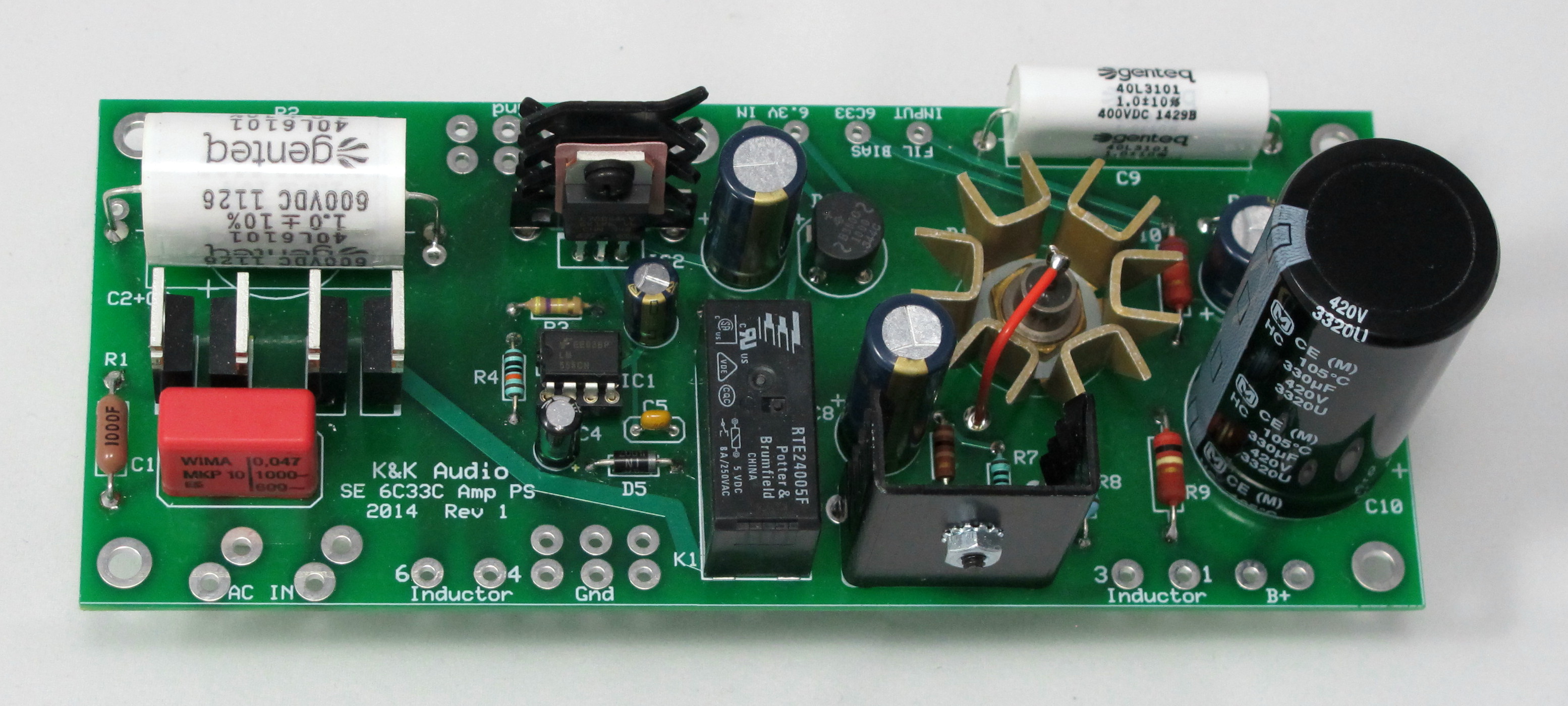
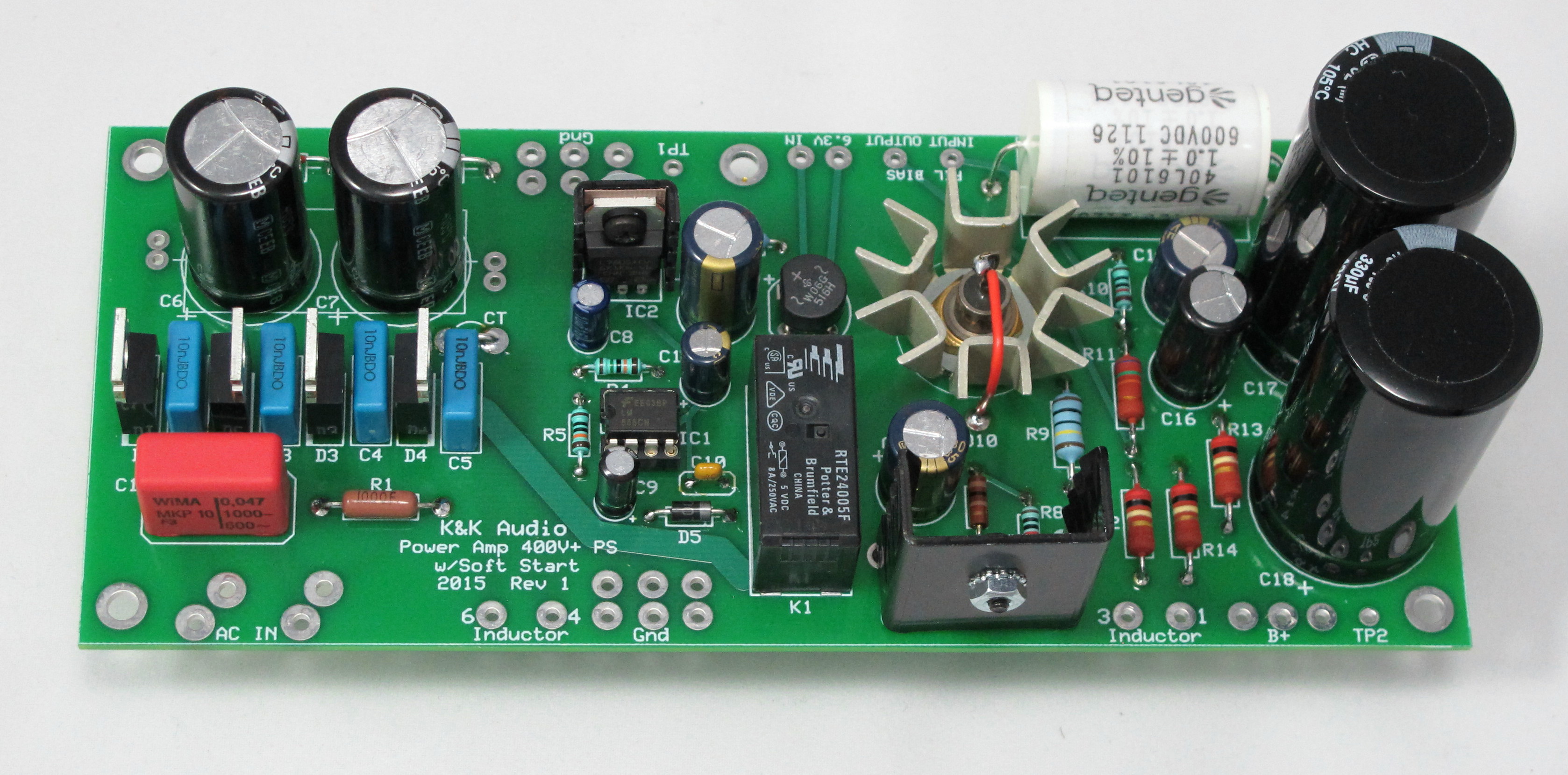
In single-ended amplifiers, it’s common to use a tube rectifier for both rectification and “soft start”, meaning allowing the high voltage to rise slowly over a few seconds. This reduces stress on some components, but, more importantly for the composure of you and your speakers, eliminates the often quite loud “pop” noise that accompanies the “instant” application of high voltage to the amplifier circuitry. We have incorporated the Soft Start circuit into two of these power supplies to make them advantageous for single-ended designs.
Kits covering two voltage ranges are available, 400VDC maximum output voltage and 600VDC maximum output voltage. In both cases all parts are supplied to implement either a choke input or capacitor input power supply topology (with the exception of the choke, of course)
All of the power supply kits below use FRED diodes for rectification and can be configured to work with both traditional center-tapped power transformers and more modern power transformers lacking a center tap. A very heavy ground trace is provided with two star grounding points to which you can solder up to six ground connections each. Two filament bias pads are also provided to bias the filament supply voltage of an input tube(s) and an output tube(s) above their respective cathode voltages for longest tube life. These are also adjustable by changing resistors. Provision has been made on the board to connect Lundahl power supply chokes to form either an LC or CLC power supply with the choke connected in the common mode connection. Any other appropriate power supply choke can be used with any of the kits, but without the sonic advantage of the common mode connection.
The Amplifier Power Supply Kits all require a 6.3-12VAC supply to power the time delay/soft start functions. The resulting DC supply is not referenced to ground, so a 6.3V filament winding could even be shared between the PS board and a tube. The current consumed is about 200mA.
Of course, you will need to supply a suitable power transformer and, optionally, a choke to make these fully functional.
Lower Voltage Amplifier Power Supply Kit, with Soft Start, 400VDC output or less
- Maximum Output: 400VDC @ 600mA
- PC board is 2.6” (6.6cm) x 6.2” (15.8cm). The assembled power supply requires about 2.1” (5.3 cm) clearance above the PC board and 0.5” (1.3cm) below the PC board.
$99
Higher Voltage Amplifier Power Supply Kit, with Soft Start, 600VDC output or less
- Maximum Output: 600VDC @ 600mA
- PC board is 2.9” (7.4cm) x 6.9” (17.5cm). The assembled power supply requires about 2.1” (5.3 cm) clearance above the PC board and 0.5” (1.3cm) below the PC board.
$125
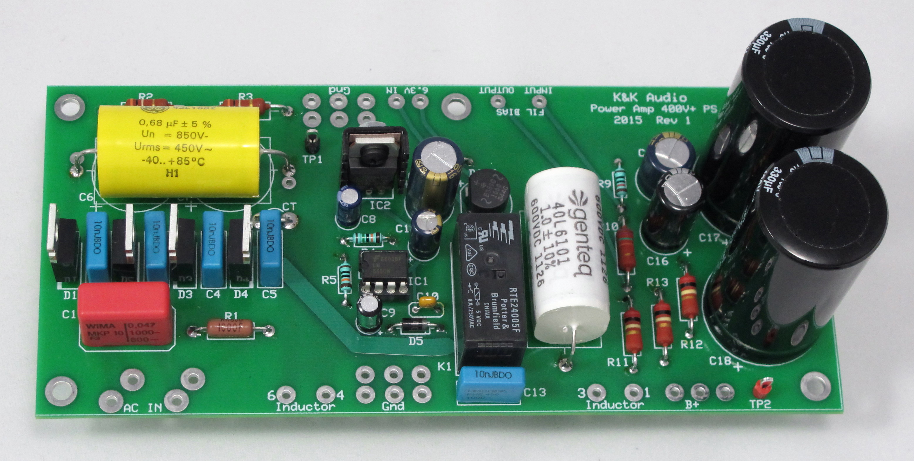
Higher Voltage Amplifier Power Supply Kit, no Soft Start, 600VDC output or less
- Maximum Output: 600VDC @ 600mA
- PC board is 2.9” (7.4cm) x 6.4” (16.3cm). The assembled power supply requires about 2.1” (5.3 cm) clearance above the PC board and 0.38” (0.9cm) below the PC board.
$110
K&K Audio Dynaco Stereo-70 Amplifier Upgrade Kit
“Jillions” of Dynaco Stereo-70 amplifiers were made and sold in the 60s and 70s, both assembled and as kits. David Hafler worked a bit of magic in the design of this amplifier. The output transformers are relatively complex in winding structure, the chassis solid, if undistinguished looking, and the original tubes supplied superb (Mullard EL-34s for much of the 60s), all for $99 as a kit!
A used Dynaco Stereo-70 was my first tube power amplifier (way back in 1982). I made the usual capacitor substitutions and other “improvements” and used it until my EICO HF89 came along a few years later. The HF89 sounded better primarily, in my view, because the input stage circuit was better. In 1990, I was fortunate to participate in a listening panel of several ST-70 mods compared to an original (see the article by David Davenport in the first issue of Glass Audio magazine). This opened my ears to the potential that the basic components (transformers and chassis) in the amplifier have for the DIYer. This upgrade is radically different from the others that have been and are available, in that the signal phase splitting is performed in an input transformer rather than by a tube stage. While much has been made of the band limiting and distortion characteristics of transformers in the audio press over the last 50 years, it is my experience that the sound quality that results from phase splitting in a properly designed input or interstage transformer easily exceeds that achieved by even the highest tech tube phase splitting circuit. The performance of the transformer within its bandwidth is very consistent, rendering very accurate phase splitting from well below 20Hz to well above 20KHz. In addition, the input transformer provides galvanic isolation between the source and the amplifier, removing the possibility of ground loop hum involving the power amplifier, a common problem in audio systems. The input transformer is followed by a 6N23P (6922) differential stage that drives the output tubes through coupling capacitors. This stage, often referred to as a “long-tailed pair driver” is made as “linear” as possible by “standing” it on a high impedance common cathode current source to provide for true differential action. The 6N23P input stage provides relatively high gain and very symmetrical drive to the output stage at a moderately low impedance. The output stage is configured as a differential push-pull stage by connecting both of the cathodes of the output tubes to a pair of paralleled current sources. Output tube bias is adjusted by means of setting the current sources for the bias current of your choice; so it is independent of tube brand, characteristics, or age. Operating the output stage differentially also means that the output tubes “track” each other dynamically (as well as their initial matching allows). This lowers distortion and dramatically improves sound quality. The output stage can be set up to operate either in the partial triode (“ultralinear”) or pure triode mode, depending on whether the screen grid is connected to the plate or the output transformer primary tap. A special screen grid network is used to improve sound quality in either case. No global feedback is used, or required, for great sound.
As a result of using a true differential output stage, the output stage operates in Class A1. This results in a very robust sonic presentation that belies the low (triode connected) test bench power rating (see table of specs below). In fact, the kit modified ST-70 sounds far more powerful than a stock unit does. Lest you forget, the “70” in the model number denotes 70 watts output for both channels. Test bench numbers clearly don’t tell the whole story! A K&K Audio Kit modified ST-70 provides dynamic performance in a moderate size room with 89dB-91dB speakers and can credibly drive lower sensitivity speakers, as well.
The other consequence of using current sources to set the output stage tube bias is the ability to “drop-in” other output tubes with the same basing configuration as the original EL34 without having to readjust bias. The current sources control the tube bias current rather than the tube. Other tubes that can be used with the kit include the 6550, KT-88, KT-90, KT-100, KT-120, 6L6GC, and KT-77.
The power supply is made simple by virtue of the good power supply rejection provided by differential amplifiers. The original tube rectifier has been replaced by FRED solid state rectifiers and a time delay high voltage turn-on circuit. A minus voltage supply is also included for the input stage current sources and uses the original transformer’s bias tap. The PC board has been very carefully laid out with a “star” grounding system for the best sound.
Mk II – A New Power Transformer, Bigger Heat Sinks and More Power Output
The power transformer (as well as output tube and bias current) you choose will have a direct bearing on the power output of your amplifier. Roughly speaking (with all other things equal), the maximum power output in a tube amplifier correlates to the raw high voltage DC power supply voltage. So, for example, if you increase the power transformer high voltage secondary from 400VDC to 500VDC, the maximum output power will increase by about 500/400 squared, which is 1.5 times! Furthermore, if you increase the output tube bias current you get an approximately proportional increase in power output there, as well. With the original power transformer, the highest bias current that I could recommend would be 55mA, to avoid damaging the transformer, but with a new specially-designed power transformer, well…
The K&K Audio Upgrade Kit has certainly exceeded my very modest sales expectations over the past 4 years, so I was interested in addressing its most critical weakness in the average system and that is power output. So I worked with a U.S. transformer manufacturer who could make a higher voltage and higher current power transformer that will fit into the same footprint as the original. They did a great job of hitting the voltage and current specs resulting in a power transformer that will nearly double the power output compared to the original kit with an original power transformer. To squeeze out every precious watt of output power with this new transformer, I also found a commercial heat sink that would mount on the PC board with the radiating area necessary to dissipate the heat of the added cathode voltage and current without expanding the footprint of the PC board.
The short story is that you can now get 14w/ch into 4 ohms and 26w/ch into 8 ohms with the Mk II Kit, the new “SST-70” power transformer and a quad of Tung-Sol KT-120 output tubes.
The measured specifications of a Mk II amplifier equipped with an SST-70 power transformer, KT-120s and the Lundahl LL1682/PP output transformers are:
- Frequency response at 1 watt into a 4 ohm resistive load: -1.4dB @ 20Hz and -0.2dB at 20KHz, with -1dB frequencies (relative to 1KHz) of 24Hz and 52KHz.
- Power output at symmetrical clipping of a 1KHz sine wave is 14 watts into a 4 ohm resistive load and 26 watts into an 8 ohm resistive load. Absolutely no ringing or overshoot at clipping.
The ST-70 Upgrade Kit Contents
The kit includes all of the parts (including the tubes) necessary to populate a single circuit board that replaces the original Dyna circuit board, the large power supply capacitor, and the bias potentiometers.
Modifying an Original ST-70 the K&K Audio Upgrade Mk II Circuitry
You will need to supply an original Dyna ST-70 with functional output and power transformers. If you use an original ST-70, then the only parts that are reused in the upgraded amplifier are as follows:
- Power switch
- Speaker screw terminal strips (unless you replace them with conventional binding posts (discussed below)
- RCA jacks (unless you replace them with better RCA jacks as discussed later)
- Fuse holder
- Line cord grommet
- Output transformers (2)
- Power transformer
- Output tube sockets (4)
- Output tubes (4)
- Chassis parts, including hardware for attaching bottom and cage
The rest of the original parts are removed and “recycled”.
If your original ST-70 comes with a “dead” power transformer or output transformer, these can be replaced with replica transformers from either DynaKitParts, Triode Electronics. The power transformer and/or output transformers can also be dramatically upgraded with parts supplied by K&K Audio, as explained below.
Building a “New” ST-70 with the K&K Audio Upgrade Mk II Circuitry
If you want to start with all new parts to build your modified ST-70, then the list of parts above is still valid. Chassis that are either pretty faithful copies of the original or modified to reflect more modern connectors (audio and power) are available from DynaKitParts, Triode Electronics, or Tubes4HiFi. The Triode Electronics chassis is the most modern with respect to connectors, but also uses the thinnest steel of the three above and doesn’t have a cover available. All are fabricated of stainless steel, so rust is not likely to trouble your new ST-70 as it does the original.
Recommended Output Tubes and Bias Currents
With more choices comes complication, so here are recommended amplifier output stage tubes and bias limits to go with the power transformer choices available. The Mk II Kit will work well with any of the combinations detailed in the table.
| Power Transformer |
Recommended Output Tubes |
Maximum Bias Current (mA per tube) |
Power Output (watts into 4 ohms) |
| Original PA060 | EL34, KT77, 6L6GC, KT-88, 6550 |
55 |
8 |
| Modern replacements | EL34, KT77, 6L6GC, KT-88, 6550 |
60 |
9 |
| K&K Audio SST-70 | KT-90, KT-120 |
75 |
14 |
These maximum bias current recommendations reflect the use of an amplifier without a cage in a room with an ambient temperature of no more than 80 degrees F (27 degrees C). If you must use a cage or your room is significantly warmer than this temperature, you will need to reduce the maximum bias recommendations by at least 5mA-10mA. For those of you who must use a cage, your heat sink will be shorter than that shown below in order for it to fit under the cage and you will need to purchase a quiet fan kit that installs on the top of the heat sink. Even with a heat sink fan, your tube life will be reduced significantly by the higher temperatures around the output tubes that the reduced ventilation causes.
Last, But Certainly Not Least: Upgraded Output Transformers
Lundahl recently developed a cover that will allow the smaller 40w Lundahl output transformers (LL1682/PP) to fit nicely in place of the stock ST-70 output transformers, so I couldn’t resist. I was more than rewarded for my trouble with a dramatic increase in sound quality, most noticeably, a more dynamic, lively and open presentation that was both detailed and easy to listen to for hours.
A heavy paper template and drill bits will be provided with the LL1682/PP transformers and covers ordered to aid in drilling new mounting holes. Alternatively, you can send a new or old unpopulated chassis to me for drilling for a flat fee of $25 plus return shipping.
Pair of Lundahl LL1682/PP output transformers with Lundahl Covers: $395
Mk II Upgrade Kit Configurations
The Upgrade Kit is available in various parts configurations to meet various budget and performance needs. The Mk II ST-70 Upgrade Kit uses the excellent cobalt amorphous core LL1544A for phase-splitting and is available with either Cardas coupling capacitors for ultimate transparency and resolution or Jensen copper foil/paper in oil coupling capacitors for a warmer, yet still detailed sound. The kit can also be purchased without coupling capacitors (needs 4 x 0.1uF 400v-600v) for those of you who have other preferences based either on past experience or current fads. (:=))
The Mk II Kit can be ordered with or without the Shunt Regulators described below.
Mk II Upgrade Kit with Cardas coupling capacitors: $395
Mk II Upgrade Kit with Jensen copper foil/paper in oil coupling capacitors: $445
Mk II Upgrade Kit without coupling capacitors: $360
In addition to the kits, there are several optional items available to make your modified kit more functional in a modern audio system. Both the RCA jacks and the screw-type speaker terminal strip are not really very useful with today’s interconnects and speaker cables. We have engineered a PC board to fit in place of each of the two octal sockets mounted on the front of the chassis. The bias check points are no longer required, so the sockets are discarded and these holes are reused as new RCA jack mounting holes with the aid of the PC boards. We have also designed another small PC board that fits in the rectangular cutout covered by the screw-type speaker terminal strip that has three holes in it to locate three binding posts for each channel (normally used for the common, 4 ohm and 8 ohm output transformer taps) with the industry standard 0.75″ spacing. You may also want to replace the output tube sockets with new ceramic base sockets.
High quality gold plated brass RCA jacks (2) with PC mounting boards and hardware: $12
Gold plated speaker binding posts (6) with PC mounting boards: $32
Replacement Ceramic Octal Output Tube Sockets (4): $24
Quiet Heat Sink Fan Kit: $25
SST-70 High Voltage / High Current Power Transformer: $170
Pair of Lundahl LL1682/PP output transformers with Lundahl Covers: $395
A Mk II assembled circuit board ready for installation is shown above. The circuit board (5.1″ (13cm) x 7.6″ (19.3cm) attaches to the chassis using original screw holes and supplied hardware.
The completed installation of the PC board, SST-70 power transformer, Tung-Sol KT-120 Output Tubes, and Lundahl Output transformers onto a Triode Electronics chassis is shown.
Shunt Regulator Upgrade for Dynaco ST-70 Upgrade Kit
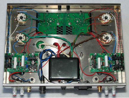 I’ve been experimenting recently with simple shunt regulators used to support differential amplifier stages like the input stage on the K&K Audio ST-70 Upgrade Kit. I’ve been pleasantly surprised with the results, which were uniformly positive and of such a magnitude that you didn’t have to listen closely to hear them. The words in vocal recordings were immediately easier to understand and complex music became easier to sort out. My impression was that of lower perceived distortion, giving the modified ST-70 more resolution at all listening levels.
The upgrade kit combines a cascode constant current source of the same variety as we sell individually with a simple 3 transistor shunt regulator that is similar to the one developed by Salas that you can view at http://www.diyaudio.com/forums/power-supplies/134801-simplistic-mosfet-hv-shunt-regs.html. These two circuits are configured on one PC board that is used for each channel of the ST-70 and mount underneath the chassis using the front bolts that hold each output transformer. A few parts have to be removed/replaced on the main K&K Audio PC board to electrically accommodate the regulator and 3 wires have to be added between each of these boards and the main board. A picture of the shunt regulator implementation is shown. All electronic parts, wire, and hardware for the modification are provided in the kit.
Shunt Regulator Kit for K&K Audio ST-70 original or Mk II Upgrade Kit $79
Octal Time Delay Relay
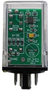 To get even more out of your original K&K Audio modified ST-70, we’ve developed an octal base plug-in time delay relay to replace the GZ-34 that’s used solely in the modified ST-70 amplifier as a turn-on delay. Getting rid of the GZ-34 increases the supply voltage for a couple more watts of output power and lowers the power supply impedance for better dynamic performance. You must have already installed the Shunt Regulator Upgrade Kit for this Time Delay Relay to fit and you cannot use it to substitute for the GZ-34 in any other design that uses a GZ-34 as a high voltage rectifier. The Octal Time Delay is not used with the Mk II Upgrade Kit.
Octal Time Delay Relay (assembled and tested) $30
Show and Tell
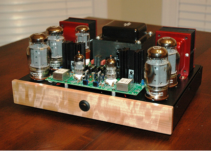 For an idea of what can be accomplished cosmetically with this kit and a Stereo-70, look at the unit constructed by Trent Weaver of Cary, NC. He had the chassis powder coated with a matte black finish and spray painted the output transformer end covers with “Jaguar red” paint. After moving the RCA jacks to the back panel and the power switch to the front panel, Trent cut a thin piece of makore (“African cherry”) to fit the front and attached it with screws from the inside for a finished look.

